Cable Stayed Bridge
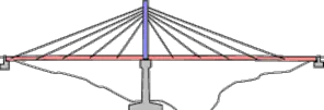
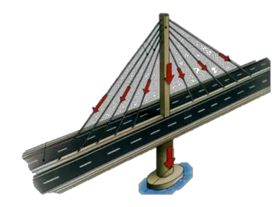
A typical cable stayed bridge is a continuous girder with one or more towers erected above piers in the middle of the span. From these towers, cables stretch down diagonally (usually to both sides) and support the girder.
Steel cables are extremely strong but very flexible. Cables are very economical as they allow a slender and lighter structure which is still able to span great distances. Though only a few cables are strong enough to support the entire bridge, their flexibility makes them weak to a force we rarely consider: the wind.
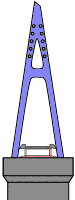
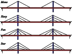
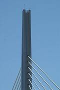
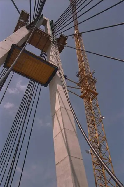
Pylons
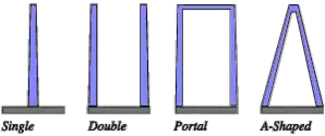
The pylon may be fabricated from steel plate, or precast concrete elements or occasionally in in situ concrete. The various configurations shown, in figure below illustrate the flexibility of design options available to produce good aesthetic effect.
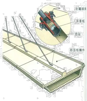
Deck
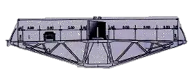
- Like the pylon, the superstructure may be assembled in precast concrete elements, steel plate or girders, or made in in situ concrete
- The most common form being the box section, which offers good torsion restraint.
- Trusses are also an option but the high fabrication costs, expensive maintenance to counteract corrosion and poor aerodynamic characteristics now render this method relatively uneconomic.
- Plate girders are sometimes used where erection procedures require assembly in small light elements.
Fixing Of Cables
- Parallel Arrangement Design
- Radial Attatchment Design
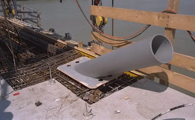
The Cable And Connections
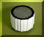
- The cable material is similar to that used for normal prestressing work and either comprises multi-strand cable made up of cold drawn wires or alternatively as single strand cable (mono-strand cable) consisting of parallel wires
- Diameters in the range 40-125 mm are typical
- Protection against corrosion can be provided by galvanizing each wire, but a more thorough practice has been to cover the cable in steel or plastic ducting and subsequently inject cement grout after positioning in place. This latter operation is carried out after all dead loads have been applied to avoid too much-cracking of the mortar
- The cable is normally connected to the pylon with pin-type joints as illustrated in the examples shown in the figure above or alternatively placed in the groove or guide tube of a saddle, depending upon the design requirements.
- The cable ends for the pin-type connection have either swaged or filled sockets. Swaging consists of squeezing a socket onto the wire in a hydraulic press and is generally used with strand having a diameter in the range 10-40 mm
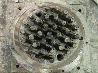
- Filled sockets are more suited to the larger diameter parallel wire type cable with the socket containing the whole bundle of wires. Several alternative types are manufactured differing slightly in the form of dead ending of each wire and the type of filling material
- In the most simple form the wires are led through a plate at the base of the socket and finished with a button head. The inside of the socket, conical in shape, is subsequently filled with an alloy of zinc, copper, aluminum or lead, or sometimes with a cold casting compound such as epoxy resin. Thu! when the cable is subject to a tension load, wedging action develops thereby increasing the grip on the wires.
- The deck-to-cable connection is usually of the ‘free’ type to accommodate adjustment.. Initial tensioning of the cable to remove slack is generally carried out with a hydraulic jack, the socket is therefore often manufactured with at internal thread for the jack connection and external thread and nut to take up the extension and other adjustments
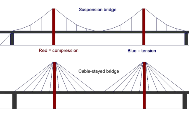
Difference Between Cable Stayed And Suspension Beidges
- Cable-stayed bridges may look similar to suspensions bridges—both have roadways that hang from cables and both have towers. But the two bridges support the load of the roadway in very different ways. The difference lies in how the cables are connected to the towers. In suspension bridges, the cables ride freely across the towers, transmitting the load to the anchorages at either end. In cable-stayed bridges, the cables are attached to the towers, which alone bear the load
- The principle aim of the structural configuration of a cable-stayed arrangement, is to prevent sideways and vertical movements of the tower/pylon and deck under asymmetrical live loading. By careful selection of the foundation types and connection of cable and girder it is possible to maintain stability of the whole structure by resisting only the horizontal and vertical components of the forces generated.
Leave a Reply
You must be logged in to post a comment.