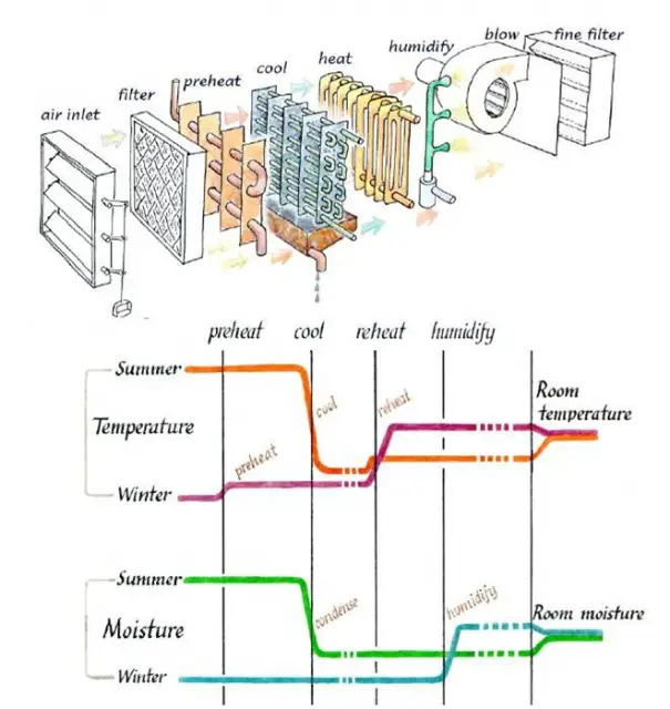
HVAC systems consume an important part of the building construction budget & account for a major portion of a typical building’s annual energy consumption. An Air Conditioning System must: accomplish 4 objectives:
- Control air temperature
- Control air humidity
- Control air circulation
- Control air quality
|
Gross Floor Area
( Ft.2)
|
Domicile Related Occupancies
|
Institutional Occupancies
|
Assembly Based Occupancies
|
Laboratory Occupancies
|
|
10,000
|
6%
|
8%
|
9%
|
11%
|
|
50,000-1,00,000
|
4%
|
6%
|
7%
|
10%
|
|
5,00,000
|
3%
|
4%
|
5%
|
8%
|
 |
 |
|
|
Source Components
|
 |
|
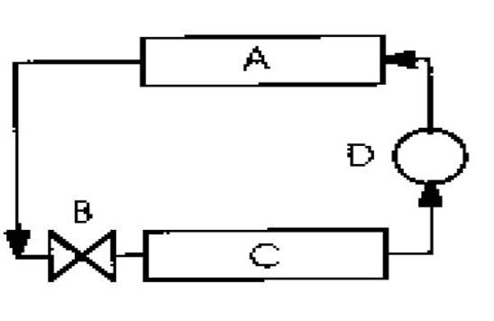
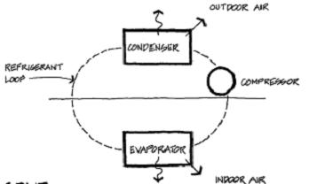
The most commonly used active cooling approach involves
the operation of a vapor compression refrigeration cycle to
induce heat to move in a direction contrary to gross
environmental temperature differences
|
||
 |
 |
|
|
Components of vapour
compression refrigeration cycle:
A – condenser
B – expansion valve
C – evaporator
D – compressor
|
|
|
|
Source Components
the basic concept is same as vapour compression unit, however
the means of execution is substantially different.
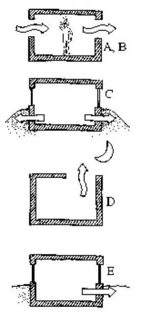
Water, acting as the refrigerant, is circulated between a generator,
a condenser, an evaporator, and an absorber
The dry air is passed through some porous media that is wetted with water. As the air contacts the water spread over the media, much of the water evaporates.
Where climate permits, evaporative cooling can provide an energy-efficient (but water-consumptive) means of building cooling.
|
 |
|
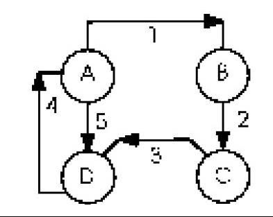
Schematic operation of absorption refrigeration cycle:
A – generator B – condenser
C – evaporator D – absorber
1 – refrigerant gas (water vapor)
2 – liquid refrigerant (water)
3 – refrigerant gas
4 – mixture of refrigerant and salt solution
5 – concentrated salt solution
|
|
Source Componenets
¢DX Systems
1.In direct expansion system the evaporator of the refrigeration
cycle is placed in an air handling unit so that the room cooling
effect is produced directly by room air flowing across the
vaporator.
2.Window air-conditioners, unitary or through-the-wall
air conditioners, rooftop package units, and split systems
are typically DX systems
2.Capacity control in a chilled water system is usually achieved
through modulation of water flow through the coils.
4.Vapor compression chillers may utilize reciprocating, centrifugal,
screw, or rotary compressor configurations.
|
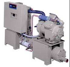 |
|
Indoor water cooled reciprocating chiller
200 tons
|
|
 |
|
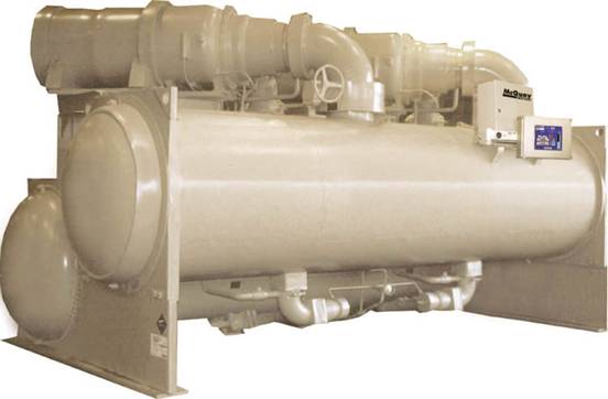
|
Single circuit centrifugal compressor chiller
250-2500 tons
|
|
Source Components
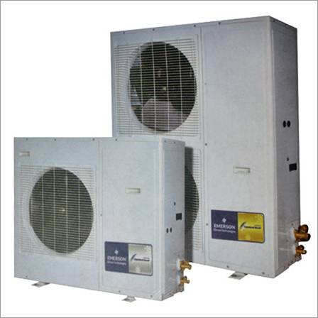
¢Air-Cooled Condensers
1.Heat rejection device, installed outside of the building envelope,
through which refrigerant is circulated.
2.As the refrigerant comes into indirect contact with outside air,
heat is exchanged from the relatively hot refrigerant to the relatively
cooler air.
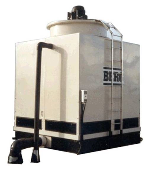
1.Heat rejection device, installed outside of the building envelope,
through which condenser water is circulated
2.Refrigerant in the refrigeration cycle is condensed in a
refrigerant-to-water heat exchanger. Heat rejected from
the refrigerant increases the temperature of the condenser water,
which must be cooled to permit the cycle to continue
4.A cooling tower is a latent heat exchanger, where the magnitude of heat flow is a function of the quantity of water that is evaporated — which is primarily a function of the relative humidity of the outside air.
|
 |
|
Air Cooled Condenser
|
|
 |
|
|
Cooling Tower
|
Local Systems
- ¢They serve a single thermal zone
- ¢Only one point of control
- ¢Greater collective reliability as compared to central air conditioners
- ¢Maintenance tends to be simpler
- ¢local systems may be totally shut off in the unused spaces, thus providing potential energy savings
- ¢greater occupant comfort through totally individualized control options
- ¢if one room needs heating while an adjacent one needs cooling, two local systems can respond without conflict
- ¢cant be easily connected together to permit centralized energy management operations
- ¢can not benefit from economies of scale
- ¢Several central
- ¢HVAC systems deliver improved efficiency and lower first cost by sharing load capacity across an entire building.
- ¢maintenance may often be relatively simple, such maintenance may haveto occur directly in occupied building
- ¢Window Air Conditioner
- 1.Packaged unit consisting of a vapour compression refrigeration cycle
- 2.Designed for installation without ductwork and can effectively distribute air only within a few feet of the unit
- 3.Several architectural concerns including aesthetics, noise, space utilization, and leakage (infiltration and water
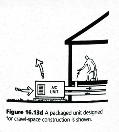
- ¢Packaged Rooftop Air Conditioner
- 1.May function as a local air-conditioning system if it is not connected to substantial distribution ductwork
- 2.The typical capacity for a rooftop packaged unit is greater than for a window or unitary air-conditioner
- 3.Packaged rooftop units are also commonly used with distribution ductwork in central systems.
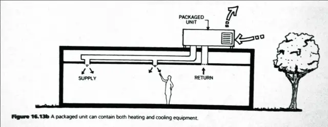 |
Packaged unit
|
 |
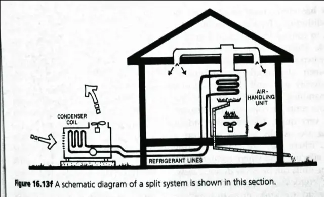
- ¢Split System
- 1.Consists of an exterior unit (consisting of compressor and condenser elements) and an interior unit (consisting of evaporator and expansion valve elements)
-
2.Arrangement permits much greater installation flexibility providing enhanced architectural and thermal opportunities
- 3.Separation distance between exterior and interior elements is usually limited to around 100 feet
Central Air Conditioning Systems
- The purpose of an air-conditioning system is to control selected air properties – this is most easily accomplished directly, through an all-air system.
•All-air systems may require extensive building volume for ductwork distribution. - In situations where ductwork can not be reasonably accommodated in the building design, air-water or all-water approaches may be considered.
- A central HVAC system may serve one or more thermal zones and has its major components located outside of the zone or zones being served.
- Space conditioning (thermal) energy from a central system must pass through zone boundaries on its way to the space or spaces being conditioned. Central HVAC systems will have as many points of control (thermostats) as there are zones.
- Water-cooled systems are more efficient than air-cooled alternatives because the temperatures produced by refrigerant condensation are lower with water than with air.
Central Air Conditioning Systems
Advantages
- •Allows major equipment components to be isolated in a mechanical room.
- •Isolating allows maintenance to occur with limited disruption to building functions.
- •Reduces noise and aesthetic impacts on building occupants.
- •Offer opportunities for economies of scale.
- •Larger capacity refrigeration equipment is usually more efficient
- •Larger systems can utilize cooling towers
- •Central systems permit building-wide load sharing
- •Reduce building energy consumption.
- •Active smoke control is best accomplished
Disadvantages
- •Failure of any key equipment component may affect an entire building.
- Specialists are needed.
- Analysis and understanding more difficult.
- The need to transfer conditioned air or water imposes space and volume demands on a building.
- •Incorporates the main benefits of all-air and all-water system.
- •Historically this has resulted in a system where 80-90 % of the space load is dealt with by cooled water and 10-20% by cooled air.
- •Distributed from a central plant to conditioned spaces via water.
- •Distribution containers (pipes) of small volume.
- •Requires a more sophisticated delivery device.
- •All-water cooling-only systems are rare.
- •Valance units and fan-coil units are the most common delivery devices.
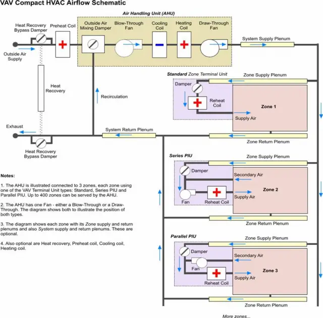
- •5 types – Single zone and multi-zone systems are constant volume, variable supply-temperature systems that are controlled at the central air handler.
- •The dual duct and multi-zone systems are multiple path systems.
- •Numerous variations, for example, induction terminal units.
- •Require that the majority of air supplied to a space is returned to the AHU for reconditioning.
- •Numerous individual heat pumps are provided.
- •A centralized water circulation loop is provided as a heat source and heat sink for the heat pumps.
- •Heat pumps act as the primary source of heating and cooling.
- •Water loop serves as a convenient place for the heat pumps to reject heat.
- •Cooling tower can be used to reject heat.
- •Chiller is not required.
- •Not energy efficient.
- •Noise concerns.
- •Ventilation concerns.
- •A small-scale AHU with circulation fan, cooling coil and filter.
- •Available for vertical or horizontal installation.
- •Exposed or concealed.
- •The cooling effect is produced by a chiller.
- •Control is achieved through control of water flow through the coil. Further by a multi-speed fan option and adjustable air louvers.
- •Ventilation is an issue.
- •Maintenance.
- •Fan noise.
- •An air-water fan-coil system can overcome this constraint.
Central Air Conditioning Systems
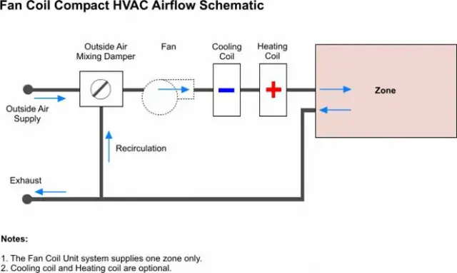
Fan-coil:
- Similar to an all-water fan-coil with one major difference – supply air from a central air handler is provided to each space as well as conditioned water.
- Supply air is to meet the ventilation needs.
Induction:
- Employs high velocity air flow from a central AHU.
- Induces a flow of room air into and through the cabinet.
- The mixture of central air and room air is conditioned in the unit.
- Filtration of the secondary room air at the induction cabinet.
Terminal reheat:
- Multiple zone adaptation of a single zone system.
- A thermostat in each zone controls the heat output of the reheat coil.
- The supply air is conditioned to cool the zone with the greatest cooling load.
- Reheat devices can be added or removed to accommodate zoning changes.
- Excellent control of thermal conditions.
- Very wasteful of energy.
Central Air Conditioning Systems
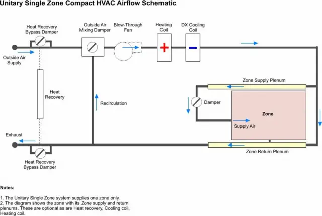
Single zone:
- Consists of an air handling unit, a cooling source, distribution ductwork, and appropriate delivery devices.
- Integrated
- Commonly a rooftop unit – access to the exterior.
- Modulating by varying the flow.
- Control is effected at the air handling unit (AHU).
- One control device (modulating or on-off ).
- Cost of installing a single zone system is low.
- Most basic and least complex of central all-air systems.
- The easiest to maintain and the simplest to design.
- Can effectively condition only one zone.
- Separate source and distribution equipment required to serve several air handlers.
- Not easily modified to serve multiple zones.
Dual duct:
- Terminal-controlled adaptation of the multi-zone concept.
- A central AHU provides two conditioned air streams.
- A terminal mixing box is provided for each zone.
- The air streams are mixed Under control.
- More flexible.
- Pros and cons similar to multi-zone system.
Central Air Conditioning Systems
|
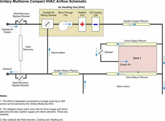
Multi-zone:
Variable volume:
|
|
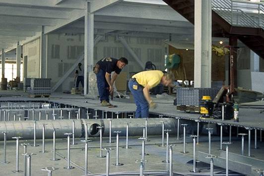
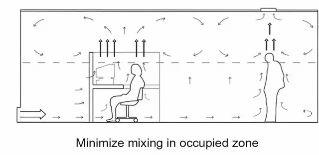
Underfloor Supply
Advantages
Disadvantages
|
 |
 |
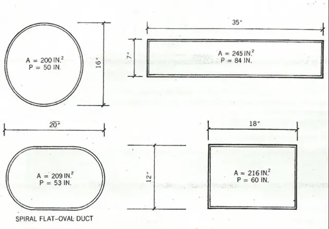
Ducts
 |
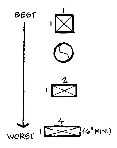 |
- Ductwork is to transport air from the AHU to each outlet in the conditioned spaces –at the specified velocity- and then back to the AHU
- The air distribution velocity can either be high (above 2500 fpm or 12.7 m/s), medium (2200- 2500 fpm or 11.2 to 12.7 m/s) or low (1000- 2200 fpm or 5.1 to 11.2 m/s)
Power Consumption
- 1 TR of refrigeration = 3024 kCal/hr heat rejected
- 1 TR/ hr. = 1.5 kWh
- Effectively, the overall energy consumption would be towards:
– Compressor kW
– Chilled water pump kW
– Condenser water pump kW
– Cooling tower fan kW, for induced / forced draft towers
- An indicative TR load profile for air conditioning is presented as follows:
Small office cabins = 0.1 TR /m2
Medium size office (10 – 30 people occupancy)= 0.06 TR/ m2
with central A/C
Large multistoried office = 0.04 TR/ m2
complexes with central A/C
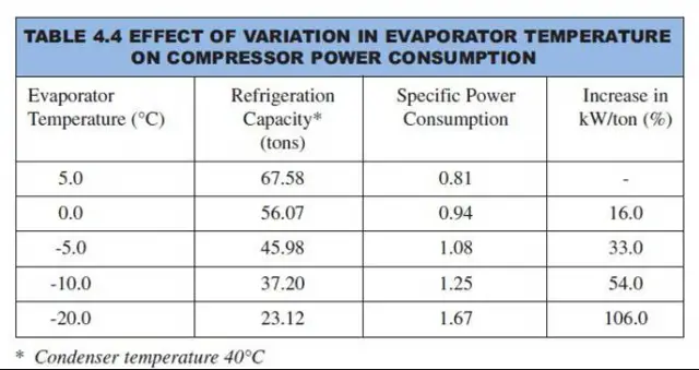
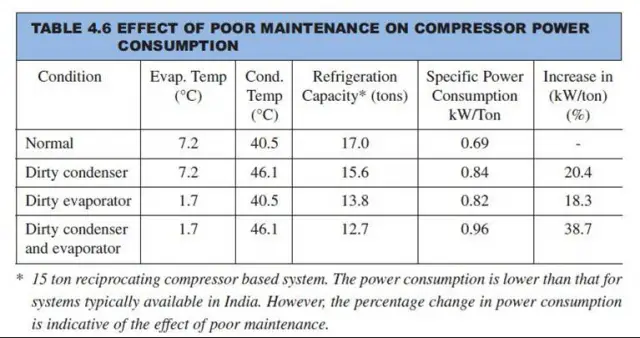
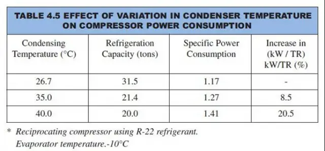
Factors Affecting Performance & Energy Efficiency
 |
 |
 |
|
Choosing An Air Conditioner Suiting Your Needs
- Measure the room’s width and length in meters.
- Multiply the length by the width, and then multiply that number by 337 to get the BTUs required to cool that space. For example, 10 meters x 10 meters x 337 = 33,700 BTU.
- Measure the windows in meters. Multiply the length and width of the windows together, and then multiply by 870 if they are south facing or 167 if they are north facing. Add the BTU for all of the windows together. For example: .5 meters x .5 meters X 167 (north facing windows) = 41.75 x 3 windows = 125.25 BTU.
- Determine the average occupancy of the room. Multiply the normal number of occupants by 400. Example: 3 people x 400 = 1200 BTU.
- Add the outcomes of Steps 1 through 4 together to get your total required air conditioning needs for that one room in your house. Pick an air conditioner that can handle the number of BTUs you calculated or more. For example, 33,700 + 125.25 + 1,200 = 35,025.25 BTU required
Leave a Reply
You must be logged in to post a comment.